Lightweight filling inside equipment
The intended function is to occupy internal equipment space with a lightweight filler. Similar applications can be explored for drone bodies, machines, vehicle housings, robotic systems and industrial equipment. Define the available envelope, neighboring components and the access that the filler must leave clear.
A 3D-printed prototype
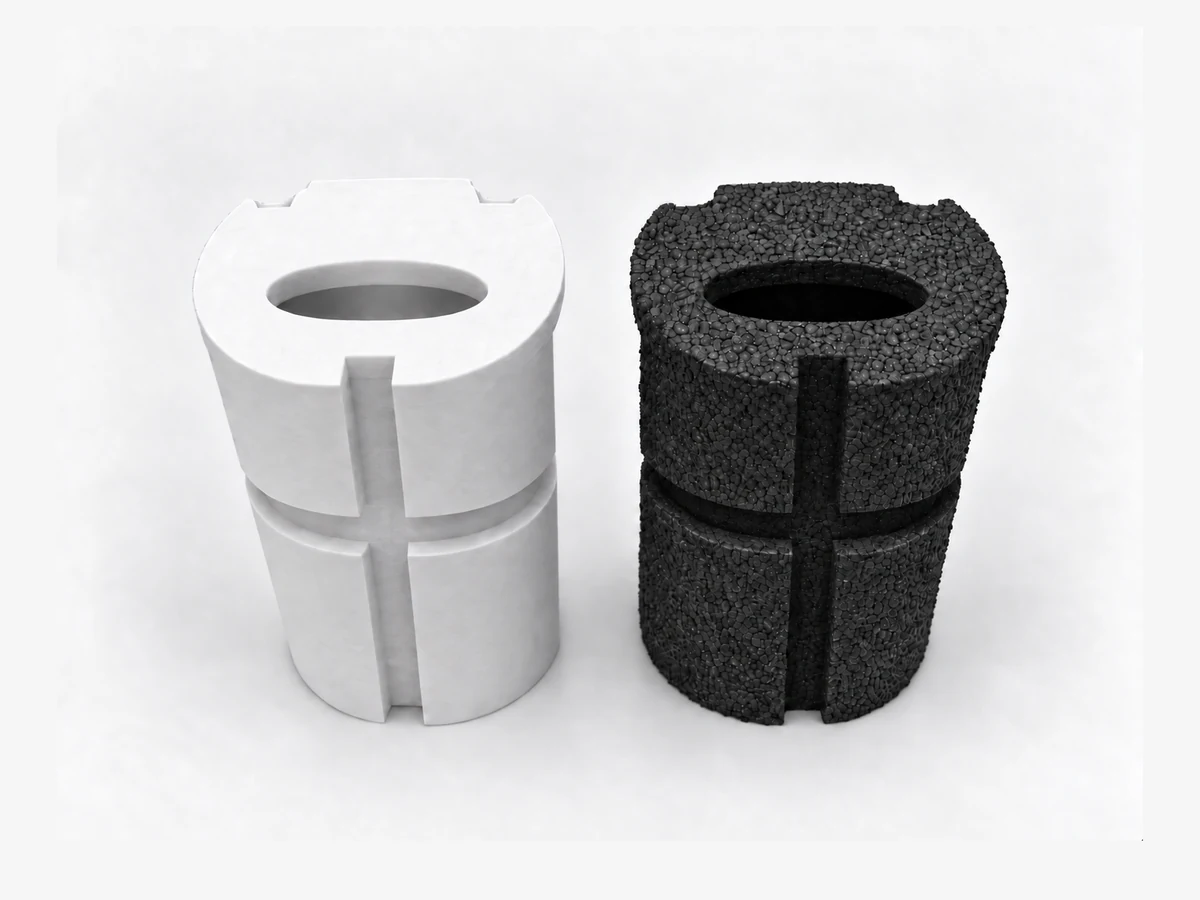
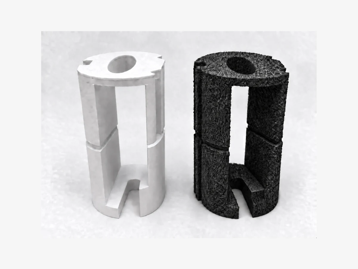
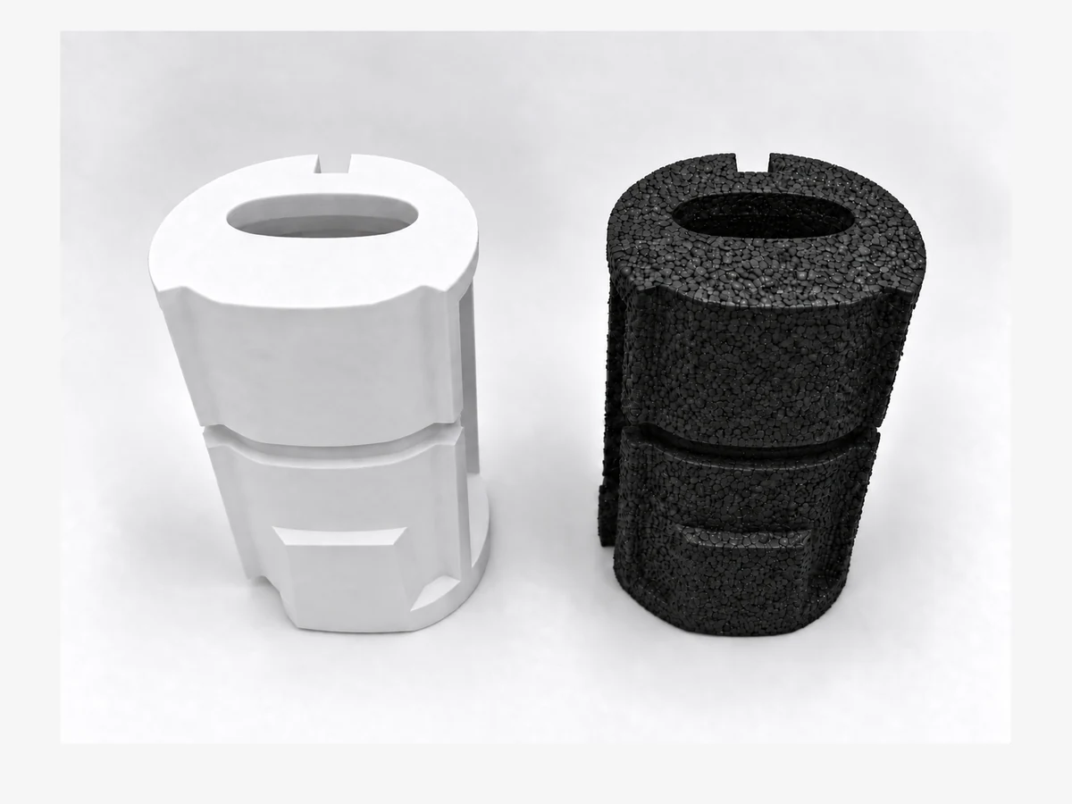
A white prototype was produced by 3D printing as a physical model of the component. It represents the prototype stage of the project. Foam material assessment belongs to the separate PE pilot stage.
A CNC-machined PE foam pilot
The black pilot was CNC machined from PE foam at 20 kg/m³. Its purpose was to assess EPE production ability and the associated feasibility conditions. CNC machining is the confirmed process for this pilot; the intended EPE production route is a separate development step.
Project outcome
The project did not progress to mass production. This example presents the prototype and pilot stages, together with the production direction considered. Further project details remain confidential; no confirmed EPE production conditions or performance test results are reported.
Define a similar application
Start with the equipment drawing or CAD, the volume to fill, the permitted added mass and the interfaces that must remain accessible. Identify assembly and removal needs, operating conditions, target quantities and the checks required before production. These are considerations for your project, to be agreed with FFG around its own specification.