
Review the 2D drawing
The drawing shows front, top, right and isometric views of the upper-cover CAD model, including its recessed panel, slots and side profile.
Starting from the customer’s original design, FFG co-developed this ABS upper cover for electronic equipment through design for manufacture (DFM). FFG managed injection-mould manufacture and part production in Asia. The 3D CAD view and 2D drawing below show the cover geometry.
Discuss a similar application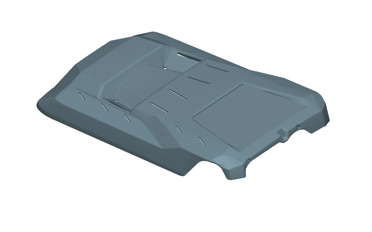
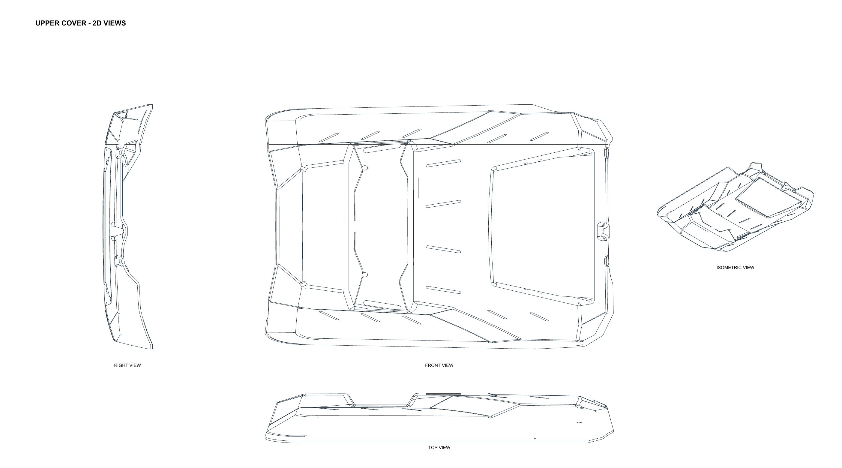
The drawing shows front, top, right and isometric views of the upper-cover CAD model, including its recessed panel, slots and side profile.
FFG worked with the customer’s starting design and developed it for injection moulding. For a similar enclosure, DFM discussion can cover wall thickness, mould release angles, ribs and fastening features, mould parting and ejection, appearance surfaces and the fit to mating components.
FFG managed the injection-mould manufacturing route and piece production in Asia for this project. For a new cover, define expected volumes, tooling ownership, sample approval, inspection points and delivery requirements early so the tool and production plan match the intended use.
Send the 3D model and 2D drawing of your cover and mating enclosure, target quantities, cosmetic requirements and operating conditions. FFG can then review the part design, tooling route and production plan with you.
Share the part or assembly drawing, overall dimensions, material or grade if known, interfaces, quantities and timing. Include the requirements you need to validate.
Discuss a similar application